Android Line Follower Mobile Robot
May 1, 2016
Overview
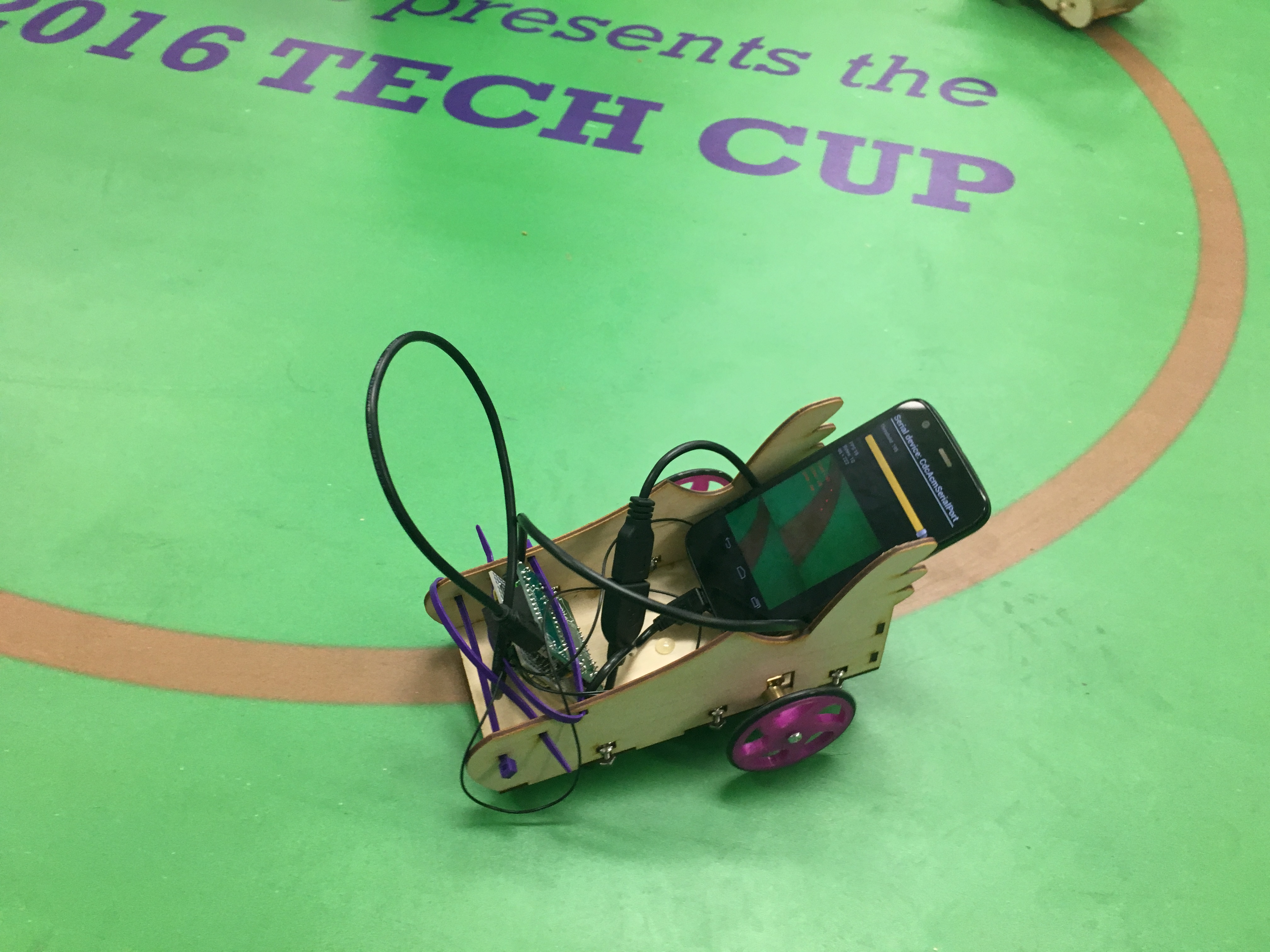
This project was part of the course Advanced Mechatronics, at Northwestern University. The goal of this project was to design, fabricate, and program a robotic cart made of laser cut and 3D printed parts and then let it automatically follow the colored line in the ground with PIC32 and USB CDC.
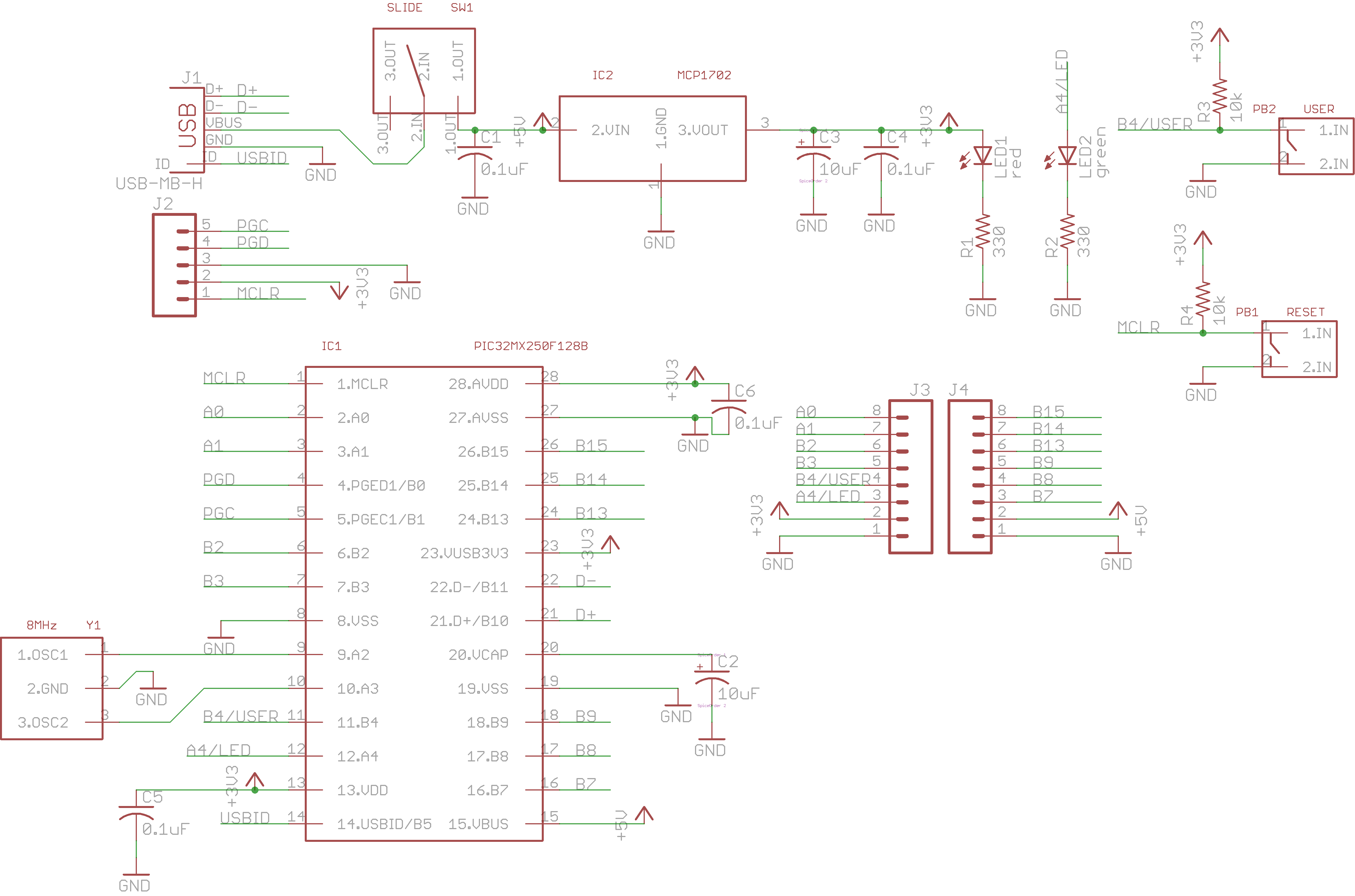
The PCB schematic shown in the image below was used:
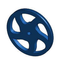
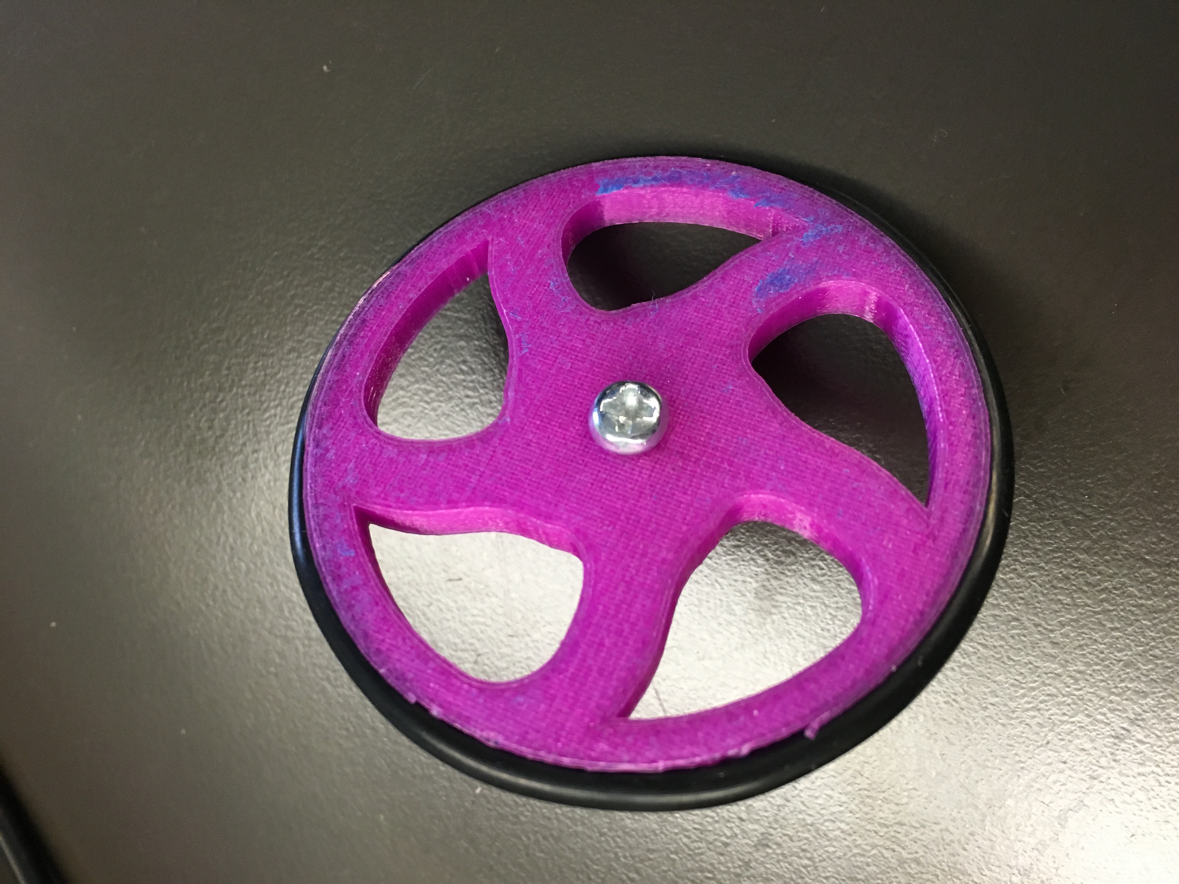
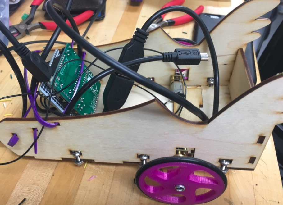
Wheels were designed via CAD and 3D printed:
Cart were designed via Solidworks and made of laser cut:
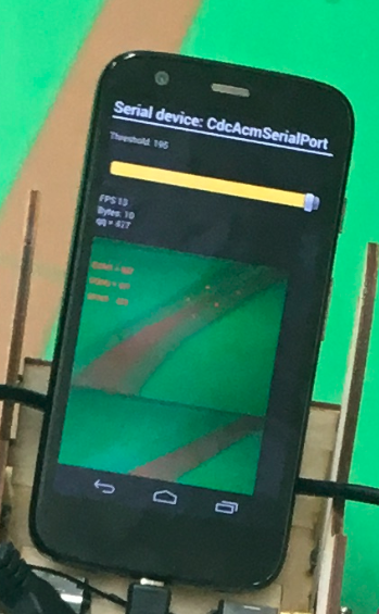
One sliders in the Android app was used to control the threshold of camera. There were 3 points on the phone screen which represented the center of mass.
The default was set to be 100% PWM output for both left and right motors. PWM of motors was changed in order to change direction. When the COM2 was larger than 320, the PWM of the right motor was decreased by (COM3-320)/320. When the COM2 was smaller than 320, the PWM of the left motor was decreased by (320-COM3)/320.
All of the code for this project is hosted on this page: Github page